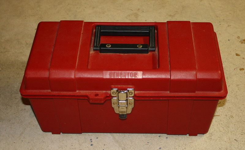
BPASA

  Boris and Paul's Aeronautics
and Space Administration

Paul's TARC team
2011 finalists!

   Home   Movies   Apollo Saturn V   Hot Rod Nitro FireBall   TOGinator   VooDoo Daddy   NERRF   Rocketflite MF tests
   Soyuz and Thunderbird links on Home page, plus:  HellBoy   Turbine Rocket Saucer   Fireworks   Cluster Box

Cluster Box                 
Rocketry Forum thread

KiloWatt+ output > electric sledge hammer > lightning in a box
light weight - designed to fire large clusters

1300+ watt output from a 6 pound box.   Click on any picture to enlarge.

Purpose:
To boost electrical power available to fire clustered rocket projects.
Requirements:
1) Very high current output (100+ amps) with minimal voltage sag - powerful enough to easily fire 30+ igniters
2) Light weight so it can be easily carried with the rocket to the launch pad

Design:
After listening
to John Lyngdal's presentation at NARCON 2010, I came to more fully appreciate the amount of voltage drop typically present during a cluster launch and its negative effects on igniter timing and reliability.

Resistance of power wiring is critical. In most launch systems there is more voltage drop due to power wiring than the battery.

For 10 ft leads there is a 20 ft round trip for the circuit.
16awg, used in many launch systems, has 4ohms of resistance per 1000ft.
16awg, 10ft lead, 20ft x 0.004ohms=0.08ohms or about 1V drop per 12.5A current due to leads

10awg has 1ohm of resistance per 1000ft.
10awg, 10ft lead, 20ft x 0.001ohms=0.02ohms or about 1V drop per 50A current due to leads

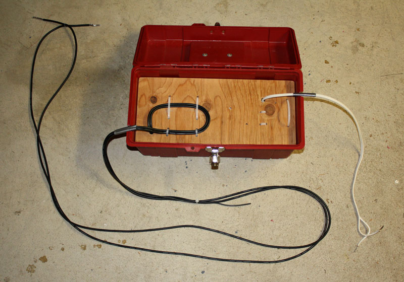
Was concerned that leads heavier than 10awg would be prone to pulling out the rocket's igniters.
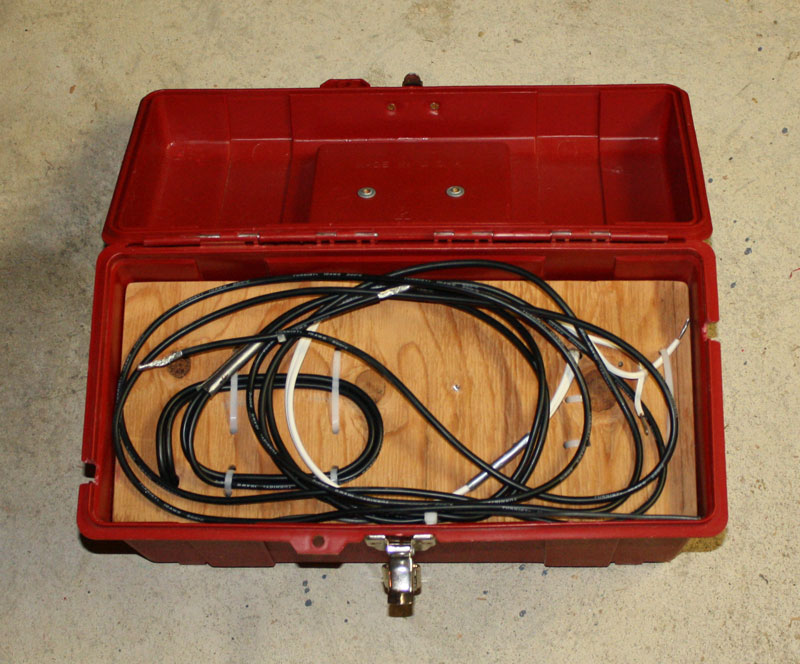
Wanted wires that could follow the rocket for 2-3 feet as it lifted off.

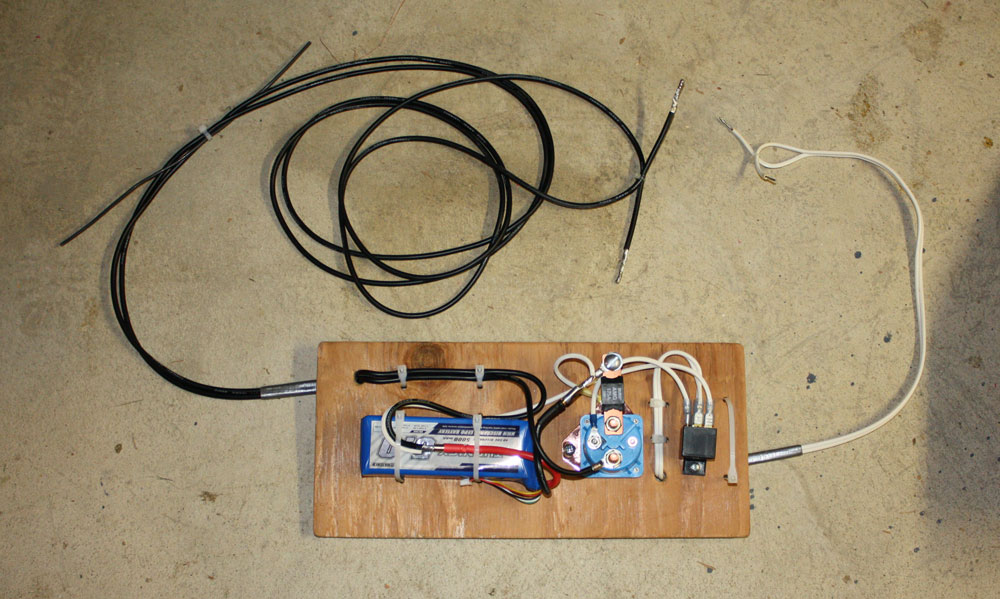
Going for simplicity and light weight, chose a high output Lipo battery and heavy gauge power wires.
Considered but did not use capacitors and lead acid batteries.

The Turnigy (hobby RC) wire has very fine strands and silicone insulation, making it far more flexible than any other 10awg wire I have ever seen.

Choose a 14.8V Lipo battery rated for very high current output (200A+) to stay compatible with 12V components and igniters while delivering lots of power from a light weight battery (only 1.3lbs).

Build:
Started with a small tool box about 14" long. Cut and sanded a 3/8 piece of plywood to sit on internal tray supports. Mounted all the electronics to the bottom and stored the wires on top of the board.

Power is a Turnigy 5.0 Ah Lipo 4S 14.8V battery, picked up from HobbyKing for $65. Battery is rated 40C (200A) continuous, 50C (250A) for 10 second bursts. As I tracked the order discovered they ship from Hong Kong.

Power wires are about 8ft long, Turnigy 10awg, very fine stranded wire with silicone insulation. Low resistance while being remarkably flexible. Soldered all high current connections and ends of wires. Used no clips or switches for simplicity and reliability.

Used a small 40A rated relay to activate the big 200A relay. Big relay purchased from partsgeek.com was 1990 Ford LTD Crown Victoria Starter Solenoid ($27). Chose this relay because it has a clamping diode and is recommended by Rocketflite. Electromagnetic field collapse in big relay creates a high voltage surge, clamping diode prevents this from hitting the smaller relay hard, smaller relay isolates cluster box from club launch system.

Bottom line:
1) cluster box weighs about 6lbs total (with 1.3lb battery and 2lb plastic case)
2) club system activates the small relay and is isolated from the rest of the system
3) a LOT of power is available on the heavy duty black power lines when needed

Tests:

Comparing performance:

Resistances created by using 1ohm resistors in parallel.
Voltages measured. Amps and watts calculated.

Launch system typical of a good club system using relay.
12.6V 22Ah AGM battery with about 10ft of 16awg power leads.
ohms volts  amps  watts
1.00 10.75 10.8 116
0.50 9.55 19.1 182
0.33 8.6 26.1 224
0.25 7.9 31.6 250


Cluster box. 14.8V rated, 15.38V measured at no load, 5Ah 40C Lipo battery, with about 8ft of 10awg power leads.
ohms volts amps watts
1.00 14.88 14.9

221

0.50 14.4 28.8

415

0.33 14.0 42.4 594
0.25 13.6 54.4 740
0.16 12.8 80.0 1024
0.10 11.4 114 1300

Crunching these numbers shows that a good typical club system has an internal resistance of 0.15ohms, while the cluster box has an internal resistance of 0.03ohms. Comparing these numbers with calculated values for the wires (in "Design" section above) shows that wire resistance is more than half of each launch system's total resistance. Internal resistance is the cause of voltage droop under load.

Comparing systems with a 0.25ohm load, club system has dropped to 7.9V and delivers 250W, cluster box is at 13.6V and delivers 740W.

When the cluster box is putting out over 1000watts its output voltage is about the same as a lead acid battery at no load.


Had to measure voltages quickly because the clusters of 10w Radio Shack resistors started smoking almost immediately due to the excessive power they were getting.

After finding that the battery charger had stopped charging due to an arbitrary timer, charged the battery fully to 16.8V and ran three more tests:

Cluster box. 14.8V rated, 16.75V measured at no load, 5Ah 40C Lipo battery, with about 8ft of 10awg power leads.
ohms volts amps watts
1.00 16.0 16.0 256
0.50 15.5 31.0 481
0.16 13.9 86.9 1208

Flight Results:
In 2010 used the Cluster box starting in July for all flights using 4+ igniters.

Fired 151 of 152 motors, in 22 cluster flights, igniting 4 to 30 motors.
The high power output of the cluster box was very effective at reliably and quickly firing igniters and rocket motors.

18 flights were entirely fired by Rocketflite ML igniters.
3 flights combined ML + CTI igniters in each HP motor for redundancy (TOGinator, Tres and HRNF).
1 flight used CTI igniter for central motor (first Thunderbird flight).

Please see Rocket MF Tests page for pictures and more information on combining series and parallel wiring of igniters.
This is done to balance voltage vs. current demands of clustered igniter system.

The one ignition failure was in the HotRod Nitro FireBall flight. This project attempts to combine a clustered launch with 6x separate second stage rockets. Due to extreme complexity, there are many opportunities for igniters and wires to be displaced or damaged during flight prep and liftoff.

Rocket Number of Flights Motors Loaded Motors Fired Igniters
(see Notes below)
Turbine Rocket Saucer 15 74 74 Rocketflite ML
(2) most flights (1) a few flights
Thunderbird 3 33 33 Rocketflite ML
mostly (2) and (3) combined
TOGinator 1 30 30 Rocketflite ML
(2) and (3) combined with both CTI and ML igniter in central I motor
Saucer of DOOM 1 7 7 Rocketflite ML
 (2) and (3) combined
Tres 1 3 3  1 Rocketflite ML + 1 CTI igniter
in each I motor
HotRod Nitro FireBall  1 7 6 Rocketflite ML
(2) and (3) combined with 1 ML + 1 CTI igniter in central H motor
Total 22 152 151  

Notes:
(1) wired all in parallel
(2) series strings of 2 then wired in parallel
(3) series strings of 3 then wired in parallel